
Turning a €250 3D Printer into a Touchscreen Test Station Worth €20k+
How a repurposed FDM printer replaced a €20k thermal-and-motion test setup — and what that says about designing automation architecture around intent, not hardware.
Originally posted on LinkedIn →At a robotics fair, over lunch, I was talking about the overlooked potential of simple robots such as CNC machines — how many problems could be solved with a bit of mechanical creativity, if people just stopped to look at them differently. Across the table, one of the attendees was listening with genuine interest: he had been facing a strikingly similar issue for weeks, and it was giving him a headache.
His company needed a way to test a new line of styluses against touchscreens. The requirements were specific:
- Draw paths on the screen to assess the sensitivity of the screen.
- Sweep across every button in the UI and verify the touch is correctly detected within and along the edges.
- Repeat all of it at different pencil inclinations — from vertical and up to 30°, with a single rotation axis, regardless of which plane it's defined in.
- Perform testing while the screen undergoes thermal stress — heat it up to near 80°C, since these devices don't always operate in comfortable environments.
He knew the existing commercial solution: a compact 6-axis arm to swing and roll the stylus, and a benchtop thermal chamber to bake the screen, with an opening for the pencil to reach in. Hardware alone — nothing integrated yet — ran around twenty thousand euros. He needed several installations, not one. The number didn't align with the budget.
I proposed a solution that cost €250 in hardware: repurpose a 3D printer into a full-featured testing station.
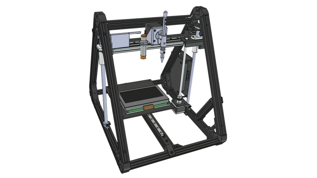
The Circular Economy of a 3D Printer
The proposal might sound weird until we stop thinking of a 3D printer in terms of features and start looking at its underlying capabilities: a 3D printer is a Cartesian robot with a fourth axis and other pre-installed tools.
Its workspace matches exactly the kind of motion the task demands: full vertical positioning to approach the screen, and planar trajectories to trace lines and sweep buttons across it. That's not a coincidence — it's the same motion profile the machine was designed to execute for every layer of every print it's ever made.
The application only requires a single rotational degree of freedom. Rotating the stylus about its own longitudinal axis has no influence on its interaction with the touchscreen, so only the inclination needs to be controlled. This significantly simplifies the mechanism compared to a general-purpose six-axis manipulator
To achieve this, the stepper motor that normally drives the printer's extruder—the fourth axis—was repurposed to rotate the stylus holder and adjust its inclination. The adaptation is simple in principle: replace what the motor drives, not how it is driven.
The heated bed solves the thermal requirement almost by accident. It's one tool that exists to keep a printed part from warping as it cools, which means it already comes with a thermistor feeding a PID loop that holds a target temperature stable — precisely the control loop an 80°C stress test needs, just aimed at a touchscreen instead of a print bed.
The hot end itself goes unused for this particular test. But its closed-loop temperature control and electronics don't disappear — they're sitting there, already wired and already characterized, waiting for whatever the next requirement turns out to be.
Four requirements satisfied by three capabilities the machine already has. The only missing piece is the software to control them — since the machine already comes with a built-in G-code processor. That's our way in.
Isn't this a great example of circular economy?
Mechanical Modification
Before diving into software layers, let's take a look at how a pencil holder replaces the extruder to control its inclination.
The picture below shows three main components:
- the stepper motor bracket;
- the eccentric wheel;
- the pencil holder, hinged to the bracket, with its eyelet engaging the wheel.
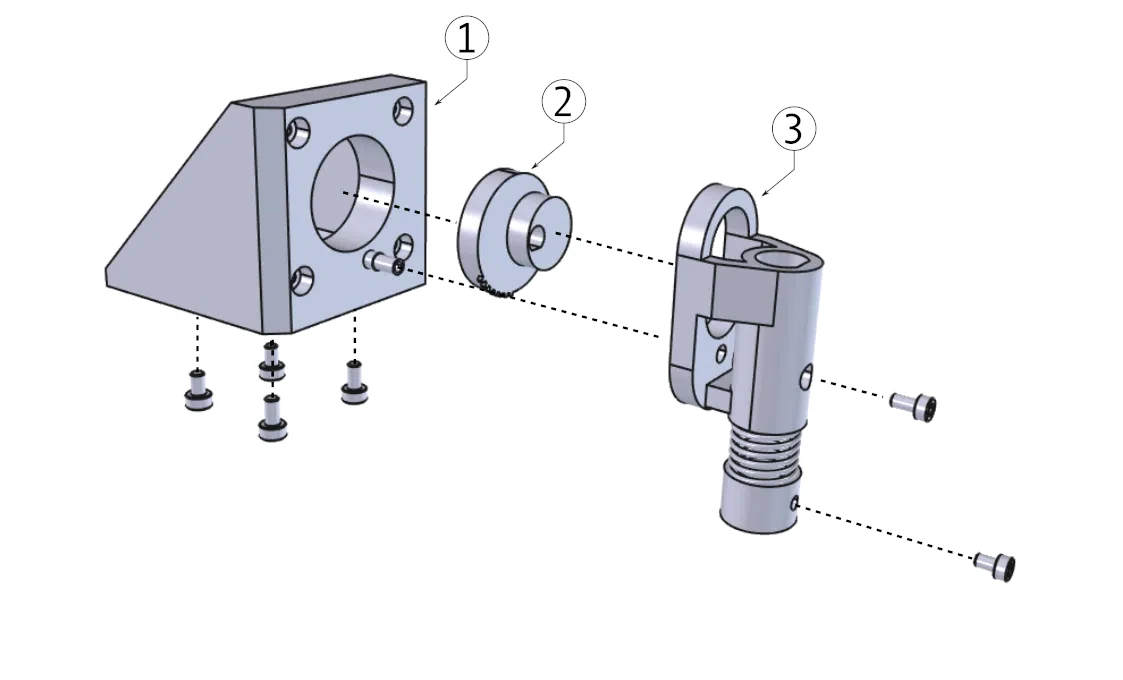
That stepper motor rotation doesn't drive the pencil holder directly. Without an encoder mounted on the motor, it would be very hard to control the orientation of the pencil, especially when the motor is de-energized. A mechanical solution compensates for this by limiting the pencil rotation range and, separately, providing a way to reset its vertical position (more on that in the Calibration section below).
The devised mechanism exploits an eccentric wheel engaging the eyelet of the pencil holder. The holder itself is hinged to a hollow pin protruding from the motor bracket, held in place by a screw threaded into the pin's cavity — this lets it rotate freely without sliding off.
As the wheel turns, the eccentric connection traces a circle; since the holder can only pivot around its fixed hinge, it's forced to follow that reciprocating motion. Stepper rotation becomes a controlled tilt range, with no software involved in limiting the angle — yet ensuring full coverage of the desired angular range.
The pencil is inserted into the holder and fixed to its base with a screw. The base sits against a compression spring that keeps the assembly preloaded and lets the pencil land gently on the touchscreen surface — more on this spring's role in Collision Avoidance below.
Speaking the Machine's Language
A 3D printer's firmware is built to execute a stream of G-code commands, usually generated offline: a CAM tool — known in the 3D printing world as a "slicer" — analyzes the target geometry, a 3D model, and generates the sequence of moves needed to produce it.
The output is G-code that is a language shared across many kinds of machines: from CNC machining centers to lathe machines, from 3D printers to desktop CNC mills and laser engravers. They all understand G-code to describe operations.
Here's the insight: 3D printers and CNC machines alike aren't wired to any particular task. They just execute basic, general-purpose motion commands. A test station, in the end, just executes another sequence of motion commands.
Turning a G-code-driven machine — a 3D printer, a CNC mill, whichever happens to be on hand — into a test station comes down to two pieces of software:
- a module that acts as a real-time CAM layer, generating G-code on the fly instead of offline from a fixed model;
- a communication layer that streams those commands to the machine continuously and reads back its feedback once each one completes.
Several off-the-shelf 3D printer firmwares already support sending G-code commands in-line, in real time, and reporting back machine status — confirming a command executed and a target position was actually reached, not just issued. That feedback loop is what turns "send a command" into "verify a test step actually happened," which is the difference between a toy and an instrument.
A standard G-code command looks like:
G01 X1 Y2 Z3G01 moves the end-effector to position (1, 2, 3) at a controlled feed rate — the right choice here, since the pencil needs to approach and contact the screen at a defined speed, not arrive as fast as the machine can manage. Because 3D printers add a fourth axis for extrusion, G-code — originally built for multi-axis industrial controllers — extends naturally with a fourth coordinate, E:
G01 X1 Y2 Z3 E4With this one command already repurposed to drive inclination instead of extrusion, a pencil mounted on a modified printer head can be swept through a full 3D workspace, at a variable angle, using nothing but the machine's own native motion language.
These commands can be enriched with further specifications, such as feed rate or units of measurement.
Some settings, like the selection between metric and imperial, apply for the whole session.
Others, like feed rate, can be defined globally and overridden per command.
For example, G01 F1 sets the default feed rate to 1 mm/min, while G01 X10 F2 overrides it just for a 10 mm move along the X axis.
Motion Abstraction Layer
For someone testing a touchscreen, the focus is on test definition and test plans — any interest in how the robot actually works is pure curiosity.
That means test definition has to be hardware-independent.
Abstraction is a well-established computer-engineering approach that consistently pays off when facing a complex system: it applies just as well here.
What we want is to let the user define any test in a six-dimensional configuration space:
- a 2D path with variable velocity, in mm and mm/s → 2 + 1 dimensions;
- distance from the touchscreen, in mm → 1 dimension;
- pencil inclination, in degrees → 1 dimension;
- bed temperature, in Celsius → 1 dimension.
Some tests require setting all of the values above; others only need to check that a certain condition is met — bed temperature below 30°C, for example. Either way, the user defines paths and distances with respect to the touchscreen surface, regardless of the machine's actual coordinate system.
Virtual coordinate system
G-code traces back to the RS-274 standard, first introduced in 1958 for industrial machinery. Machine coordinate frame versus workpiece frame is a concept G-code has always supported well — there are several user-definable coordinate systems it can handle for different combinations of workpieces and tools (G-code even supports tool-length compensation, though that's not relevant here — at least not for the first prototype).
A virtual coordinate system useful for defining machine-independent test sequences is a right-handed frame whose origin corresponds to the pencil touching a known point on the touchscreen — the bottom-left corner, for example. On most controllers, setting that reference frame is done with a command like G10 L2 P1, supplying the offset coordinates once; recalling it during a test is then as simple as invoking G54 on its own. (The exact syntax varies by firmware — worth confirming against whichever G-code interpreter your printer actually runs before relying on this.)
Linear path
Assuming machine x-y-z and test X-Y-Z are aligned and oriented the same way, the pencil's motion works out of the box once the virtual frame is set. The command
G54 G01 X10 Y0 Z1drives the pencil tip to position (x, y, z) = (10, 0, 1) with respect to the touchscreen origin, since G54 is active for this line.
Non-linear path
Complex paths can be built as a sequence of X-Y-Z points; arcs are natively supported in G-code too, with G02 and G03 handling clockwise and counter-clockwise circular interpolation.
If the machine's coordinate system isn't right-handed, or is aligned differently (Y as the vertical axis, for instance, instead of Z), a further level of abstraction is needed — a linear transformation between the user's frame and the machine's frame before generating G-code (see From Mathematical Abstraction to Heterogeneous Robotic Platforms).
Temperature
Bed temperature is typically controlled in Celsius; many firmwares let the user configure whether it's expressed in Celsius or Fahrenheit. There's little else to do here beyond mapping the high-level "set temperature" command to the corresponding G-code string.
Pencil inclination
Concerning pencil inclination — which requires the mechanical modification described above — the G-code coordinate might not match the desired unit.
We can't expect the command
G01 E-1to drive the corresponding stepper motor by exactly 1 degree counter-clockwise, even assuming the pencil is directly connected to the motor shaft with no mechanism in between.
There are two possible solutions:
- On many 3D printers, the extruder coordinate can be fine-tuned to match the extruder's own gear ratio and output a desired amount of filament. Where available, the same coefficient can be repurposed to define the conversion ratio between degrees and stepper steps — though this coefficient is sometimes limited to a small range.
- The more general solution is to apply the conversion before generating the G-code, after measuring the actual effect of
G01 E1. This can be done by extending the mathematical abstraction layer formulation described in From Mathematical Abstraction to Heterogeneous Robotic Platforms.
In the first case, after modifying the pencil's inclination, the virtual user coordinate frame must be explicitly adjusted: with inclination $\gamma$, the corresponding offset becomes $(x, y, z) = (\cos\gamma, 0, \sin\gamma)$. In the second case, that compensation is instead applied intrinsically as part of the same chain of linear transformations.
Calibration
Modern 3D printers come with an auto-calibration system — bed leveling — as a built-in feature. Typically, a touchless sensor (an inductive or capacitive probe), positioned next to the nozzle, samples multiple spots across the printing plate to build a virtual height map. This compensates for vertical-movement offsets during a print, especially on large jobs.
All printers, separately, have end-switches to home the machine.
Both systems are useful here, but for different reasons:
- Bed leveling is a nice-to-have for compensating planar misalignment between the touchscreen and the X-Y plane. It's optional, though: the same minor offset that matters greatly for a 3D printing job is nearly irrelevant for touchscreen testing.
- The homing system is the one that helps the most: before any test, the system homes, resetting both machine and user coordinate systems. Knowing the geometry of the touchscreen fixture then makes it possible to restore the user coordinate system from there.
Homing without an encoder
The fourth axis complicates this story. The stepper motor repurposed from the extruder has no encoder, so once it's de-energized there's no way to know where the pencil is actually pointing — any external force in the meantime leaves its true angle unknown. This isn't something firmware can fix on its own; it needs a mechanical answer.
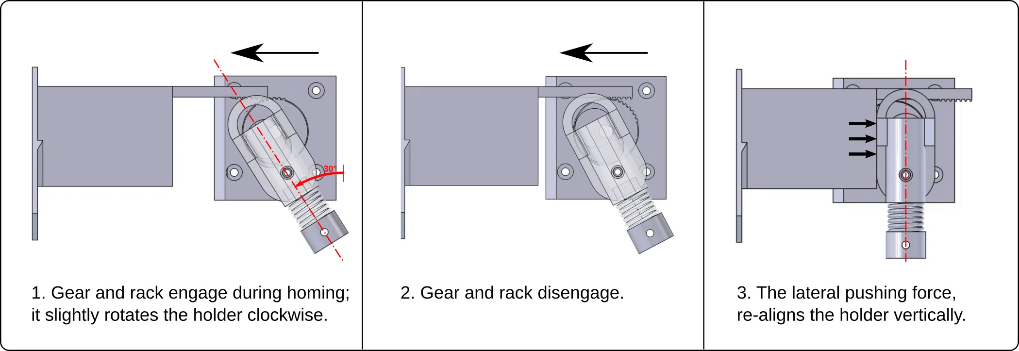
The approach is surprisingly simple. During the homing sequence, the fourth-axis motor is temporarily released while the machine first moves upward and then to the left. A fixed protrusion on the chassis applies a lateral force to the holder, causing it to rotate freely until it reaches its vertical resting position.
Unfortunately, the mechanism has one problematic configuration. At certain angles, the holder reaches a mechanical dead center where the lateral force alone cannot cause any rotation. In this condition, continuing to push against the mechanism could overstress or damage the assembly.
To eliminate this corner case, a few gear teeth were added to the rotating wheel, together with a short rack fixed to the chassis. The rack only engages the gear when the holder approaches this critical region, providing the small additional torque needed to move it away from the dead center. Once the rotation resumes, the rack disengages automatically and the holder completes its alignment under the lateral force alone.
The homing mechanism embodies the same engineering instinct as the rest of the project: whenever possible, solve the problem by exploiting capabilities that already exist — with no additional sensors and at no additional cost.
Collision Avoidance
The pencil is mounted on the fourth-axis motor shaft through a spring-loaded mechanism that does double duty: it absorbs impact if the pencil ever contacts the screen with more force than intended, and it lets the tip conform to slight unevenness in the touchscreen surface rather than requiring perfectly flat calibration.
Collision avoidance, though, needs to be handled at both the software and hardware level.
Soft collision avoidance requires a simple physical model of the system, accounting for the pencil tip and the touchscreen's outer geometry whenever a path or motion is computed. Assuming calibration is performed correctly, the software should never generate a coordinate that results in a collision. The model can get more complex if the robot's workspace allows other parts of the robot — not just the pencil tip — to contact the touchscreen; similarly, care must be taken to prevent the pencil from hitting unintended parts of the robot's own chassis.
Hard collision avoidance should intervene whenever the soft layer fails — due to miscalibration or any other unexpected situation. This works at two further levels:
- Limiting the robot's workspace by adjusting the limit switches, so the robot can only move within a predefined volume.
- Adopting mechanical "bumpers" to limit damage: mounting the pencil on a spring-loaded fixture is one example. The touchscreen itself could similarly sit on a spring-loaded support that absorbs the impact of an undesired collision.
Beyond 3D Printers
Many off-the-shelf 3D printers and CNC machines are built on third-party control boards running typically open-source firmware (Marlin or Grbl, for example). That means for prototypes where a complete Cartesian chassis isn't a necessity — e.g., a wheeled robot — those control boards, cables and stepper motors make for a valuable starting point.
Conclusion
Engineering innovation doesn't necessarily come from inventing everything from scratch. At times, it comes from recognizing capabilities that already exist and turning them into something different.
Repurposing a 3D printer to serve a completely different task, with nothing more than custom mechanical parts and a few lines of code, is one example. This worked out smoothly because the built-in G-code interface is a simple, long-established standard that can easily be used to control motion and auxiliary tools — even in real time.
More generally, this way of thinking extends well beyond 3D printers. Once software is built around geometric abstractions and hardware capabilities rather than machine-specific assumptions, new platforms become easier to integrate, cheaper to deploy and far more reusable.
Limitations
Drawbacks to be aware of:
- Existing G-code-based firmware might not be suitable for every task out of the box: when advanced control and responsiveness are required, firmware customization might be necessary.
- Processing throughput might become a bottleneck: firmware is designed for loading G-code from a previously uploaded file, and processing happens at the firmware's own pace. Sending inline commands at the sender's rate may lead to firmware instability, since the firmware might be unable to process all incoming commands — careful checks must be done on the sender's side.
- The communication stream might not be sufficient for a high data rate: G-code is usually uploaded to the machine via a serial interface, though recent models include native Wi-Fi. Keeping up with a high data rate means increasing the baud rate, which can lead to errors from noise or bad framing. A solution to this last issue can involve adopting COBS (see the article on COBS).